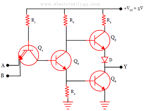
In contrast, TTL circuits minimize both of these requirements. This requires that more current be supplied to and heat be removed from RTL circuits. The obvious disadvantage of RTL is its high current dissipation when the transistor conducts to overdrive the output biasing resistor. Early IC logic production (such as Fairchild’s in 1961) used the same approach briefly, but quickly transitioned to higher-performance circuits such as diode-transistor logic and then transistor-transistor logic (starting 1963 at Sylvania), since diodes and transistors were no more expensive than resistors in the IC. The primary advantage of RTL technology was that it involved a minimum number of transistors, which was an important consideration before integrated circuit technology (that is, in circuits using discrete components), as transistors were the most expensive component to produce. RTL is the earliest class of transistorized digital logic circuit used other classes include diode-transistor logic (DTL) and transistor-transistor logic (TTL). Resistor-transistor logic (RTL) is a class of digital circuits built using resistors as the input network and bipolar junction transistors (BJTs) as switching devices. Another limitation is that RTL gates cannot switch at the high speeds used by today’s computers, although they are still useful in slower applications.Īlthough they are not designed for linear operation, RTL integrated circuits are sometimes used as inexpensive small-signal amplifiers, or as interface devices between linear and digital circuits.

However, they do draw a significant amount of current from the power supply for each gate. They also are handy because both normal and inverted signals are often available. RTL gates are almost as simple as DL gates, and remain inexpensive. This combination provides clean output signals and either inversion or non-inversion as needed. Often an additional transistor is included to re-invert the output signal. Resistor-transistor logic gates use Transistors to combine multiple input signals, which also amplify and invert the resulting combined signal.
ADVANTAGES OF TOTEM POLE OUTPUT FULL
In logic circuit diagrams the power is not shown, but in a full electronic schematic, power connections are required. Each logic gate requires power so that it can source and sink currents to achieve the correct output voltage. In electronic logic, a logic level is represented by a voltage or current, (which depends on the type of electronic logic in use). Logic gates are primarily implemented electronically using diodes or transistors, but can also be constructed using electromagnetic relays, fluidics, optics, molecules, or even mechanical elements. The logic normally performed is Boolean logic and is most commonly found in digital circuits.

A logic gate performs a logical operation on one or more logic inputs and produces a single logic output.


 0 kommentar(er)
